FreeCAD
Documentation
Section titled “Documentation”- Tutorials
- YT MangoJelly
- Tools
- When setting a property/field in an operation (e.g., the length of a pad), consider using the expression editor to reference to a previous operation’s property. See Lesson 51 mentioned below.
- Duplicate selected object
- Unlinked AFAIK.
- Also works if you have already consumed the object (e.g., a sketch).
- Carbon copy: use if you want a sketch that is linked to another sketch in the same part.
- Draft workbench Clone tool: use if you want to quickly clone a few (consumed) sketches (and scale them all (e.g., for an additive or subtractive loft operation) or to reuse them elsewhere).
- They will remain linked, so changing the original sketch will update the clones.
- If you want them unlinked, then just use a regular copy and paste (or duplicate).
- Using them elsewhere at 36:00 in this video.
- Part design clone tool: select a feature or body and create a clone of it. This “branches” out from the point cloned in the history (this is like inheritance; we set up a template body and then extend that in a clone body; when the parent changes, the child updates). Earlier operations in the original body are linked to the clone, and thus updated.
- ShapeBinder: use if you want to import geometry (can be multiple objects in one go, e.g., selecting two circles) from one part into another. You set up the ShapeBinder and then 1) use external geometry in a sketch, or 2) apply operations directly on the ShapeBinder.
- ShapeBinders can be updated: https://www.youtube.com/watch?v=01Yzz5fd_b4
- ShapeBinders can also be used for master sketches.
- Can also be used to “bind” multiple shapes into one. E.g., when you have multiple sketches that together form a single line you want to “pipe” across.
- Datum planes and datum lines: can be attached onto by other objects. The datum objects themselves are also attached, and can be moved and angled (just like any map mode attachment). Planes can be useful to attach sketch onto. Lines can be useful to define direction, e.g., for a polar pattern around it (you can also of course use an edge as the reference in a polar pattern).
- https://www.youtube.com/watch?v=n0lG1hYV1SE&list=PLWuyJLVUNtc3UYXXfSglVpfWdX31F-e5S&index=44
- Also consider using it for mirroring (across for your datum plane).
- These can also function as external geometry.
- Recommendation is to only use these for advanced polar and mirror patterns and advanced attach needs. Most of the time you can get by using the attachment modes on your objects.
- Link tool: use to bring a linked copy of a part into another document. E.g., as a rough visual reference.
- https://youtu.be/HC-0MT973NY?feature=shared&t=236
- In the video it was not used for external geometry.
- Dimensioning tool video
- It is quite versatile. Use
mto toggle between modes.- These modes sometimes also include vertical and horizontal constraints (vertex + vertex), angle (edge + edge), the equality constraint (edge + edge), and a symmetry constraint (vertex + edge).
- Didn’t know:
- clicking on a edge by itself will allow you to set dimensions for that edge’s two vertices.
- selecting a single vertex will dimension to the center point, a neat trick is to press
mto set both the horizontal and vertical distance in one go. - you can also dimension directly between the edge of a circle and another vertex (e.g., for an offset from the circle’s outermost point).
- arcs also have multiple modes.
- 3 points can lead to, among others, symmetry
- two circles have special interactions. vertex + vertex has different constraints than edge + edge.
- It is quite versatile. Use
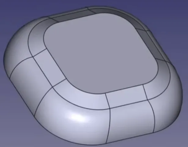
- Pipe and sweep (e.g., Tupperware container)
- https://www.youtube.com/watch?v=TZCF7HVoU74&list=PLWuyJLVUNtc3UYXXfSglVpfWdX31F-e5S&index=12
- The sub-shape binder allows you to import geometry from one part into another. You can directly consume the ShapeBinder (e.g., with a Pad) or import it as external geometry in a sketch. The ShapeBinder will update if the original geometry (in the other part) is updated.
- Can also come from another file.
- ShapeBinders can import parts, feature of parts, sketches, faces, edges, vertices, etc.
- For example one of the uses in the video above, is that we take the top face of the container cube itself, then ShapeBinder that such that we can use that as the bottom of the lid cube (we pad it out).
- Sketch attachment
- https://www.youtube.com/watch?v=kbTj9Nucpq4&list=PLWuyJLVUNtc3UYXXfSglVpfWdX31F-e5S&index=13
- Right click the sketch, open the attachment editor. Then set a point as the first reference, and a line as the second reference. Set the mode to “Normal to Edge”.
- More on attachment modes
- Sketches and “draft 2D strings” https://www.youtube.com/watch?v=Ft-yURL0Qwo&list=PLWuyJLVUNtc3UYXXfSglVpfWdX31F-e5S&index=18
- Sketches on non-planar curved surfaces https://www.youtube.com/watch?v=0zUUwyWPMQU&list=PLWuyJLVUNtc3UYXXfSglVpfWdX31F-e5S&index=19
- Just set sketch’s attachment to the curved surface’s two curved edges as references.
- Set up a scaffolding sketch, then add another sketch and attach it “Normal to Edge” to your scaffold sketch.
- Hole operation
- https://www.youtube.com/watch?v=PIAhmIuTid8&list=PLWuyJLVUNtc3UYXXfSglVpfWdX31F-e5S&index=20
- Allows you to choose ISO standard threaded holes. Set “threaded”, “Model Thread”, and “Update thread view”.
- You do not necessarily need a sketch (if you do, then the size of a circle in that sketch is ignored), instead if you have a circular face, then you can apply the hole operation to it directly.
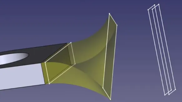
- Lofts
- https://www.youtube.com/watch?v=v689Ii71TnE&list=PLWuyJLVUNtc3UYXXfSglVpfWdX31F-e5S&index=22
- https://www.youtube.com/watch?v=sgzKC5moK_M&list=PLWuyJLVUNtc3UYXXfSglVpfWdX31F-e5S&index=23
- For a circle, it can be useful to use the ~ “Split edge” tool to add vertices to the circle.
- You might want to add a similar sketch at a small offset to manipulate the loft (see screenshot).
- Carbon copy can also be useful. It will retain the datum constraints set by the original sketch.
- This is as opposed to selecting a sketch and “Duplicate selected object”, that will be an unlinked sketch.
- https://wiki.freecad.org/index.php?title=Sketcher_CarbonCopy: Dimensional constraints which exist before the copy function remain linked to the original sketch’s dimensional constraints through expressions.
- E.g., for the ends of the twisted part you see above.
- If you want a loft to end in a point, then that is easy for the end (just add a sketch with 1 point), but the begin is used to determine the number of vertices used in the loft, so instead you just have to make it very small.
- Alternatively, again use the “Draft workbench clone tool” discussed above.
- https://www.youtube.com/watch?v=hoq2Mr59T8c&list=PLWuyJLVUNtc3UYXXfSglVpfWdX31F-e5S&index=25
- Note that instead of a loft, sometimes you can use the taper option in the pad operation. The tapered surfaces might be planar, which means it’s easier to attach subsequent sketches to. See https://www.youtube.com/watch?v=zEKnaifbI6I&list=PLWuyJLVUNtc3UYXXfSglVpfWdX31F-e5S&index=30
- Fillet that tapers to a point: use a subtractive loft with a point (and a profile that has an arc).
- Pipes and sweeps
- The path used need not be a sketch, it can also be an already existing edge of a part.
- Threads (additive helix; screw)
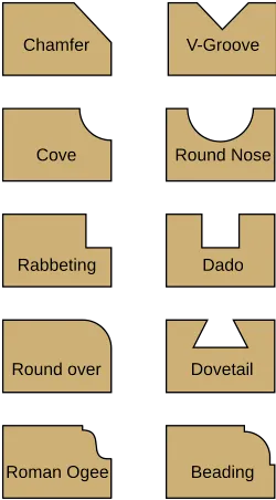
- Dress up features
- Fillets, chamfers, draft angle, thickness, etc. also smart use of subtractive pipes/lofts (see lesson 50) to achieve more complex dress up.
- These features offer more than just aesthetic tweaks. E.g., distribute stress across a larger surface, safety (less sharp), easier assembly (e.g., sunk screw holes). They also affect manufacturability (e.g., a draft angle allows easier ejection from a mold/cast).
- What are FreeCAD Dress up features? And Why Do We Need Them? | Basic Beginners FreeCAD Lesson 49
- Custom Edges in FreeCAD: Fillets, Chamfers, and Pipes | Basic Beginners FreeCAD Lesson 50
- Part Design : Drafting Angles | Basic Beginners FreeCAD Lesson 51
- He shows how an operation’s setting (e.g., a draft’s angle) can reference the value of an earlier operation’s setting. When setting the value, click on the expression editor, then type the name of the previous operation and then the name of the setting (e.g.,
Draft.Angle, orPad.Length) - Shows how the Draft feature can be used. Can be useful for working with casts/molds but also as a general way to modify the shape of the object.
- A draft can be applied to multiple faces, and you can also set a neutral plane.
- General mold making rule: “Add at least 1% of draft for every 25mm (~1 inch) of cavity depth”. So expressions could be used to automatically compute this draft angle based on the height of the pad.
- He shows how an operation’s setting (e.g., a draft’s angle) can reference the value of an earlier operation’s setting. When setting the value, click on the expression editor, then type the name of the previous operation and then the name of the setting (e.g.,
- Tools
- Move transform / array
- https://www.youtube.com/watch?v=zEKnaifbI6I&list=PLWuyJLVUNtc3UYXXfSglVpfWdX31F-e5S&index=30
- He uses construction geometry to guide where the copies should go and how much space is in between them.
- Boolean operations in part design
- https://www.youtube.com/watch?v=Z41Qx7453zk&list=PLWuyJLVUNtc3UYXXfSglVpfWdX31F-e5S&index=34
- See the video when you are dealing with moving the bodies. AFAIU the non-active bodies can be transformed (moved), not the active body.
- It can also be useful to use a Draft workbench clone, scale that up slightly, and then subtract that using a boolean operation (e.g., when you’ve modelled an electrical motor and are creating a mount for it.). The scale serves as an offset, ensuring the mount is large enough.
- After you make the clone, you’ll need to create a new body that uses that as the base.
- https://www.youtube.com/watch?v=lptN2xipSBE&list=PLWuyJLVUNtc3UYXXfSglVpfWdX31F-e5S&index=35
- Cloning can be useful when you want to consume (in a boolean operation) a body multiple times.
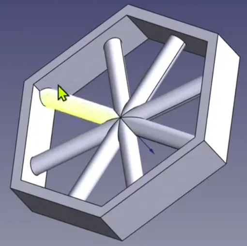
- Boolean operations + Subshape binders to restrict a volume inside a profile
- AKA useful for “creating pattern features that need to stay within a certain boundary”.
- https://www.youtube.com/watch?v=cudxRdw-31A&list=PLWuyJLVUNtc3UYXXfSglVpfWdX31F-e5S&index=37
- Bodies
- First body is the outer rim
- Then a second body that has the spokes sticking out to all sides.
- Then a third body, which contains the inside edges of the outer rim as subshape binder. Pad that out. Then perform an AND on this inside volume body and the spokes body.
- End result is just the outer rim body and the boolean inner spokes body.
- VarSet and suppressed
- VarSet variables can be used to set datum constraints and in patterns.
- Patterns need at least 1 occurrence. The pattern feature can be suppressed (this means if it fails it is just ignored) conditionally. Right click the suppressed field and click “Expression”. Then use a ternary that results in 1 or 0 (these represent the boolean state), e.g.,
VarSet.LengthUnits > 1 ? 0 : 1.- It has to be nested for AND
VarSet.LengthUnits > 1 ? (VarSet.WidthUnits > 1 ? 0 : 1) : 1.
- It has to be nested for AND
- Patterns can be applied to
- one feature
- multiple features in one go.
- Note that the order of the features matter (Ctrl selection in the model tab or the order in the Mirror tool window).
- a whole body
- Video
- You can also mirror over a plane (e.g., a face).
- Use a Multi-Transform if you want multiple patterns on top of each other (e.g., for a grid linear columns, then linear rows).
- This also has a scale transform. It will apply to the transform above it in the multi-transform list.
- Pattern along a path
- Use of a path sketch, “hole” sketch, Draft workbench’s Path link array, and shape binder.
- The path link array has start and end offset options.
- The path link array will be outside the body. Use a shape binder to be able to use it inside a body.
- Video - Patterning Along a Path in FreeCAD Part Design
- Notes on Assembly Workbench
- Notes on 2D draft plans (svg, image, etc.) to 3D model.
- FreeCAD: Converting 2D Plans To 3D. The Very Basics!
- Traced Photo to 3D Print: FreeCAD Repair Workflow Explained
- In the image properties window there is a calibrate button to size the image based on a line.
- Hexagon pattern - Using 3D printer slicer hexagonal infill as feature of the model
- Variants
- Spreadsheet and variants
- FreeCAD How To Generate Multiple Variants Automatically With Spreadsheet | Basic Beginners Lesson 52
- There must be an even faster way, but at least this is a solution. For a huge number of variants perhaps directly use the FreeCAD Python interface.
- FreeCAD How To Generate Multiple Variants Automatically With Spreadsheet | Basic Beginners Lesson 52
- Body properties and variants
- FreeCAD How To Generate Multiple Variants Without Re-Modeling | Basic Beginners Lesson 53 (FCv1.1)
- They mention using
hrefto deal with cyclic reference errors. E.g.,href(Body.Backtooth). - “Property -> Status -> Copy on Change” and “Link Copy on Change” are used.
- They mention using
- FreeCAD How To Generate Multiple Variants Without Re-Modeling | Basic Beginners Lesson 53 (FCv1.1)
- Spreadsheet and variants
- “Design Thinking” https://www.youtube.com/watch?v=c-VQfnXr4eE&list=PLWuyJLVUNtc3UYXXfSglVpfWdX31F-e5S&index=15
- Shows a diagram that guides you in decomposing an object into FreeCAD operations (to reduce the total number of iterations, thus simplifying your model; e.g., sweep first then extrude).